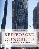
Reinforced Concrete Mechanics and Design 7th Edition by James Wight 0134183371 9780134183374
$50.00 Original price was: $50.00.$25.00Current price is: $25.00.
Reinforced Concrete Mechanics and Design 7th Edition by James Wight – Ebook PDF Instant Download/Delivery: 0134183371, 9780134183374
Full download Reinforced Concrete Mechanics and Design 7th Edition after payment
Product details:
ISBN 10: 0134183371
ISBN 13: 9780134183374
Author: James K. Wight
This is the eBook of the printed book and may not include any media, website access codes, or print supplements that may come packaged with the bound book. For courses in architecture and civil engineering. Reinforced Concrete: Mechanics and Design uses the theory of reinforced concrete design to teach readers the basic scientific and artistic principles of civil engineering. The text takes a topic often introduced at the advanced level and makes it accessible to all audiences by building a foundation with core engineering concepts. The Seventh Edition is up-to-date with the latest Building Code for Structural Concrete, giving readers access to accurate information that can be applied outside of the classroom. Readers are able to apply complicated engineering concepts to real world scenarios with in-text examples and practice problems in each chapter. With explanatory features throughout, the Seventh Edition makes the reinforced concrete design a theory all engineers can learn from.
Reinforced Concrete Mechanics and Design 7th Table of contents:
1 Introduction
1-1 Reinforced Concrete Structures
1-2 Mechanics of Reinforced Concrete
1-3 Reinforced Concrete Members
1-4 Factors Affecting Choice of Reinforced Concrete for a Structure
1-5 Historical Development of Concrete and Reinforced Concrete as Structural Materials
Cement and Concrete
Reinforced Concrete
Design Specifications for Reinforced Concrete
1-6 Building Codes and the ACI Code
References
2 The Design Process
2-1 Objectives of Design
2-2 The Design Process
2-3 Limit States and the Design of Reinforced Concrete
Limit States
Limit-States Design
Basic Design Relationship
2-4 Structural Safety
2-5 Probabilistic Calculation of Safety Factors
2-6 Design Procedures Specified in the ACI Building Code
Strength Design
Plastic Design
Plasticity Theorems
2-7 Load Factors and Load Combinations in the 2014 ACI Code
Terminology and Notation
Load Factors and Load Combinations
Load Combinations
Earthquake Loads
Dead Loads That Stabilize Overturning and Sliding
Load Factor for Small Live Loads
Lateral Earth Pressure
Self-Straining Effects
Strength-Reduction Factors, ϕ
Flexure or Combined Flexure and Axial Load
Other actions
2-8 Loadings and Actions
Direct and Indirect Actions
Classifications of Loads
Loading Specifications
Dead Loads
Live Loads Due to Use and Occupancy
Classification of Buildings for Wind, Snow, and Earthquake Loads
Snow Loads, S
Roof Live Loads, Lr, and Rain Loads, R
Construction Loads
Wind Loads
Earthquake Loads
Self-Equilibrating Loadings
Other Loads
2-9 Design for Economy
2-10 Sustainability
2-11 Customary Dimensions and Construction Tolerances
2-12 Inspection
2-13 Accuracy of Calculations
2-14 Handbooks and Design AIDS
References
3 Materials
3-1 Concrete
3-2 Behavior of Concrete Failing in Compression
Mechanism of Failure in Concrete Loaded in Compression
3-3 Compressive Strength of Concrete
Core Tests
Strength of Concrete in a Structure
3-4 Strength Under Tensile and Multiaxial Loads
Tensile Strength of Concrete
Standard Tension Tests
Relationship between Compressive and Tensile Strengths of Concrete
Factors Affecting the Tensile Strength of Concrete
Strength under Biaxial and Triaxial Loadings
Biaxial Loading of Uncracked, Unreinforced Concrete
Compressive Strength of Cracked Reinforced Concrete
Triaxial Loadings
3-5 Stress–Strain Curves for Concrete
Tangent and Secant Moduli of Elasticity
Stress–Strain Curve for Normal-Weight Concrete in Compression
Equations for Compressive Stress–Strain Diagrams
Stress–Strain Curve for Normal-Weight Concrete in Tension
Poisson’s Ratio
3-6 Time-Dependent Volume Changes
Shrinkage
Creep of Unrestrained Concrete
Restrained Creep
Thermal Expansion
3-7 High-Strength Concrete
High-Performance Concrete
Mechanical Properties
28-Day and 56-Day Compression Strengths
Shrinkage and Creep
3-8 Lightweight Concrete
3-9 Fiber Reinforced Concrete
3-10 Durability of Concrete
3-11 Behavior of Concrete Exposed to High and Low Temperatures
High Temperatures and Fire
Very Cold Temperatures
3-12 Shotcrete
3-13 High-Alumina Cement
3-14 Reinforcement
Hot-Rolled Deformed Bars
Grades, Types, and Sizes
Mechanical Properties
Fatigue Strength
Strength at High Temperatures
Welded-Wire Reinforcement
3-15 Fiber-Reinforced Polymer (FRP) Reinforcement
Properties of FRP Reinforcement
3-16 Prestressing Steel
Problems
References
4 Flexure: Behavior and Nominal Strength of Beam Sections
4-1 Introduction
Analysis versus Design
Required Strength and Design Strength
Positive and Negative Moments
Symbols and Notation
4-2 Flexure Theory
Statics of Beam Action
Flexure Theory for Reinforced Concrete
Basic Assumptions in Flexure Theory
Flexural Behavior
Cracking Point
Yield Point
Points beyond the Yield Point
Effect of Major Section Variables on Strength and Ductility
4-3 Simplifications in Flexure Theory for Design
Whitney Stress Block
4-4 Analysis of Nominal Moment Strength for Singly Reinforced Beam Sections
Stress and Strain Compatibility and Section Equilibrium
Analysis of Nominal Moment Strength, Mn
4-5 Definition of Balanced Conditions
4-6 Code Definitions of Tension-Controlled and Compression-Controlled Sections
Definitions of Effective Depth and Distance to Extreme Layer of Tension Reinforcement
Definitions of Tension-Controlled and Compression-Controlled Sections
Upper Limit on Beam Reinforcement
4-7 Beams with Compression Reinforcement
Effect of Compression Reinforcement on Strength and Behavior
Reasons for Providing Compression Reinforcement
Analysis of Nominal Moment Strength, Mn
Analysis of Strength-Reduction Factor, ϕ
Minimum Tension Reinforcement and Ties for Compression Reinforcement
4-8 Analysis of Flanged Sections
Effective Flange Width and Reinforcement in the Transverse Direction
Analysis of Nominal Moment Strength for Flanged Sections in Positive Bending
Determination of Strength-Reduction Factor, ϕ
Evaluation of As,min in Flanged Sections
4-9 Unsymmetrical Beam Sections
Problems
References
5 Flexural Design of Beam Sections
5-1 Introduction
5-2 Analysis of Continuous One-Way Floor Systems
Load Paths in a One-Way Floor System
Tributary Areas, Pattern Loadings, and Live Load Reductions
Pattern Loadings for Live Load
Live Load Reductions
ACI Moment and Shear Coefficients
Typical Factored Load Combinations for a Continuous Floor System
Structural Analysis of Continuous Beams and One-Way Slabs
5-3 Design of Singly Reinforced Beam Sections with Rectangular Compression Zones
General Factors Affecting the Design of Rectangular Beams
Location of Reinforcement
Construction of Reinforced Concrete Beams and Slabs
Preliminary Beam and Slab Depths for Control of Deflections
Concrete Cover and Bar Spacing
Calculation of Effective Depth and Minimum Web Width for a Given Bar Arrangement
Estimating the Effective Depth of a Beam and One-Way Slab
Minimum Reinforcement
General Strength Design Requirements for Beams
Design of Tension Reinforcement When Section Dimensions Are Known
Design of Beams When Section Dimensions Are Not Known
5-4 Design of Doubly Reinforced Beam Sections
5-5 Design of Continuous One-Way Slabs
Problems
References
6 Shear in Beams
6-1 Introduction
6-2 Basic Theory
Stresses in an Uncracked Elastic Beam
Average Shear Stress between Cracks
Beam Action and Arch Action
Shear Reinforcement
6-3 Behavior of Beams Failing in Shear
Behavior of Beams without Web Reinforcement
Inclined Cracking
Internal Forces in a Beam without Stirrups
Factors Affecting the Shear Strength of Beams without Web Reinforcement
Behavior of Beams with Web Reinforcement
Behavior of Beams Constructed with Fiber Reinforced Concrete
6-4 Analysis and Design of Reinforced Concrete Beams for Shear—ACI Code
Shear-Failure Limit States: Beams without Web Reinforcement
Design Equations for the Shear Strength of Members without Web Reinforcement
Axial Compression
Axial Tension
Circular Cross Sections.
Shear Failure Limit States: Beams with Web Reinforcement
Types of Web Reinforcement
Minimum Web Reinforcement
Strength-Reduction Factor for Shear
Location of Maximum Shear for the Design of Beams
Shear at Midspan of Uniformly Loaded Beams
High-Strength Concrete
6-5 Other Shear Design Methods
Definitions and Design Methods
Traditional ACI Design Procedure
Compression Field Theories
Shear Friction Method
Equivalence of Shears on Inclined and Vertical Planes
6-6 Hanger Reinforcement
6-7 Tapered Beams
6-8 Shear in Axially Loaded Members
Axial Tension
Axial Compression
Problems
References
7 Torsion
7-1 Introduction and Basic Theory
Shearing Stresses due to Torsion in Uncracked Members
Solid Members
Hollow Members
Principal Stresses due to Torsion
Stresses due to Torsion, Shear and Moment
Circulatory Torsion and Warping Torsion
7-2 Behavior of Reinforced Concrete Members Subjected to Torsion
Prior to Cracking
After Cracking
7-3 Thin-Walled Tube Analogies
7-4 Design for Torsion and Shear—ACI Code Approach
Area of Longitudinal Reinforcement
Value of θ
Limits on Concrete and Steel Strengths for Design
Combined Shear and Torsion
Amounts of Torsional and Shear Reinforcement
Types of Torsional Reinforcement and Its Anchorage
Minimum Torsional Reinforcement
Spacing of Torsional Reinforcement
Maximum Shear and Torsion
Crack Width Limit
Web Crushing Limit
Combined Moment and Torsion
7-5 ACI Code Design Method for Torsion
Problems
References
8 Development, Anchorage, and Splicing of Reinforcement
8-1 Introduction
Average Bond Stress in a Beam
Bond Stresses in an Axially Loaded Prism
True Bond Stresses in a Beam
Bond Stresses in a Pull-Out Test
8-2 Mechanism of Bond Transfer
8-3 Development Length
Tension-Development Lengths
Analysis of Bond Splitting Load
Basic Tension-Development Equation
Simplified Tension-Development-Length Equations
Bar-Spacing Factor, cb
Factors in Eqs. (8-10) through (8-14)
Excess Flexural Reinforcement
Compression-Development Lengths
Development Lengths for Bundled Bars
Development Lengths for Coated Bars
Development Lengths for Welded-Wire Reinforcement
8-4 Hooked Anchorages
Behavior of Hooked Anchorages
Development of Hooked Bars in Tension
Values for λ and ψ-factors, ACI Code Table 25.4.3.2
8-5 Headed and Mechanically Anchored Bars in Tension
8-6 Design for Anchorage
8-7 Bar Cutoffs and Development of Bars in Flexural Members
Why Bars Are Cutoff
Location of Flexural Cutoff Points
Effect of Shear on Bar Forces and Location of Bar Cutoff Points
Development of Bars at Points of Maximum Bar Force
Development of Bars in Positive-Moment Regions
Effect of Discontinuities at Bar Cutoff Points in Flexural Tension Zones
8-8 Reinforcement Continuity and Structural Integrity Requirements
Continuity Reinforcement
Structural-Integrity Reinforcement
Graphical Calculation of Flexural Cutoff Points
Standard Cutoff Points
8-9 Splices
Tension Lap Splices
Compression Lap Splices
Welded, Mechanical, and Butt Splices
Problems
References
9 Serviceability
9-1 Introduction
Serviceability Limit States
9-2 Elastic Analysis of Stresses in Beam Sections
Calculation of EI
Modulus of Elasticity and Modular Ratio
Transformed Section
Uncracked Transformed Section
Cracked Transformed Section
Service-Load Stresses in a Cracked Beam
Cracked-Transformed Section Analysis for Flanged Sections
9-3 Cracking
Types of Cracks
Development of Cracks due to Loads
Reasons for Controlling Crack Widths
Limits on Crack Width
Shrinkage and Temperature Reinforcement
Web Face Reinforcement
9-4 Deflections of Concrete Beams
Load–Deflection Behavior of a Concrete Beam
Flexural Stiffness and Moment of Inertia
Effective Moment of Inertia
Instantaneous and Additional Sustained Load Deflections
Instantaneous Deflections
Sustained-Load Deflections
9-5 Consideration of Deflections in Design
Serviceability Limit States Resulting from Flexural Deflections
Visual Appearance
Damage to Nonstructural Elements
Disruption of Function
Damage to Structural Elements
Allowable Deflections
Accuracy of Deflection Calculations
Deflection Control by Span-to-Depth Limits
9-6 Frame Deflections
Lateral Deflections
Member Stiffnesses
Vertical Deflections
9-7 Vibrations
9-8 Fatigue
Problems
References
10 Continuous Beams and One-Way Slabs
10-1 Introduction
10-2 Continuity in Reinforced Concrete Structures
Braced and Unbraced Frames
Design Loads for a Continuous Floor System
Transfer of Column Loads through the Floor System
10-3 Continuous Beams
10-4 Design of Girders
10-5 Joist Floors
Standard Dimensions and Layout of One-Way Joists
Reinforcing Details
10-6 Moment Redistribution
Problems
References
11 Columns: Combined Axial Load and Bending
11-1 Introduction
11-2 Tied and Spiral Columns
Behavior of Tied and Spiral Columns
Strength of Axially Loaded Columns
11-3 Interaction Diagrams
11-4 Interaction Diagrams for Reinforced Concrete Columns
Strain-Compatibility Solution
Concept and Assumptions
Significant Points on the Column Interaction Diagram
Strength-Reduction Factor for Columns
Maximum Axial Load
Derivation of Computation Method for Interaction Diagrams
Concentric Compressive Axial-Load Capacity and Maximum Axial-Load Capacity
General Case
Pure-Axial-Tension Case
Interaction Diagrams for Circular Columns
Properties of Interaction Diagrams for Reinforced Concrete Columns
Nondimensional Interaction Diagrams
Eccentricity of Load
Unsymmetrical Columns
Simplified Interaction Diagrams for Columns
11-5 Design of Short Columns
Types of Calculations—Analysis and Design
Factors Affecting the Choice of Column
Choice of Column Type
Choice of Material Properties and Reinforcement Ratios
Estimating the Column Size
Tied Columns
Spiral Columns
Slender Columns
Bar-Spacing Requirements
Reinforcement Splices
Spacing and Construction Requirements for Ties
Amount of Spirals and Spacing Requirements
11-6 Contributions of Steel and Concrete to Column Strength
11-7 Biaxially Loaded Columns
Problems
References
12 Slender Columns
12-1 Introduction
Definition of a Slender Column
Buckling of Axially Loaded Elastic Columns
Slender Columns in Structures
Organization of Chapter 12
12-2 Behavior and Analysis of Pin-Ended Columns
P−δ Moments and P−Δ Moments
Material Failures and Stability Failures
Slender-Column Interaction Curves
Moment Magnifier for Symmetrically Loaded Pin-Ended Beam Column
Effect of Unequal End Moments on the Strength of a Slender Column
Column Rigidity, EI
Design Values of (EI)eff for the Computation of the Critical Loads of Individual Columns
EI for the Computation of Frame Deflections and for Second-Order Analyses
Effect of Sustained Loads on Pin-Ended Columns
Effect of Loading History
Creep Buckling
Limiting Slenderness Ratios for Slender Columns
Definition of Nonsway and Sway Frames
Including Slenderness Effects
Summary of ACI Moment Magnifier Design Procedure for Columns in Nonsway Frames
12-3 Design of Columns in Nonsway Frames
Design Approximation for the Effect of End Restraints in Nonsway Frames
Calculation of k from Tables
Calculation of k via Nomographs
Calculation of ψ, Column-Beam Frames
Calculation of ψ, Column Footing Joints
12-4 Behavior of Restrained Columns in Sway Frames
Statics of Sway Frames
Mns and Ms Moments
12-5 Calculation of Moments in Sway Frames Using Second-Order Analysis
First-Order and Second-Order Analysis
Second-Order Analysis
Load Level for the Analysis
Lateral Stiffness-Reduction Factor
Stiffnesses of the Members
Foundation Rotations
Effect of Sustained Loads
Methods of Second-Order Analysis
Iterative P−Δ Analysis
Direct P−Δ Analysis for Sway Frames
12-6 Design of Columns in Sway Frames
Overview
Computation of δsMs
1. Computation of δsMs Using Second-Order Analyses
2. Computation of δsMs Using Direct P−Δ Analysis
3. Computation of δsMs Using Sway-Frame Moment Magnifier
Moments at the Ends of the Columns
Maximum Moment between the Ends of the Column
Sidesway Buckling under Gravity Loads
Minimum Moment
Load Case 2: Gravity plus Lateral (Wind) Loads
12-7 General Analysis of Slenderness Effects
12-8 Torsional Critical Load
Problems
References
13 Two-Way Slabs: Behavior, Analysis, and Design
13-1 Introduction
13-2 History of Two-Way Slabs
13-3 Behavior of Slabs Loaded to Failure in Flexure
13-4 Analysis of Moments in Two-Way Slabs
Nichols’ Analysis of Moments in Slabs
13-5 Distribution of Moments in Slabs
Relationship between Slab Curvatures and Moments
Moments in Slabs Supported by Stiff Beams or Walls
Moments in Slabs Supported by Isolated Columns
13-6 Design of Slabs
Steps in Slab Design
Beam-to-Slab Stiffness Ratio, αf
Minimum Thickness of Two-Way Slabs
Slabs without Beams between Interior Columns
Slabs with Beams between the Interior Supports
13-7 The Direct-Design Method
Limitations on the Use of the Direct-Design Method
Distribution of Moments within Panels—Slabs without Beams between All Supports
Statical Moment, Mo
Positive and Negative Moments in Panels
Provision for Pattern Loadings
Provision for Concentrated Loads
Definition of Column Strips and Middle Strips
Distribution of Moments between Column Strips and Middle Strips
Transfer of Moments to Columns
Exterior Columns
Interior Columns
13-8 Equivalent-Frame Methods
Classic Equivalent-Frame Analysis of Slab Systems for Vertical Loads
Calculation of Stiffness, Carryover, and Fixed-End Moments
Properties of Slab-Beams
Properties of Columns
Torsional Members and Equivalent Columns
Arrangement of Live Loads for Structural Analysis
Moments at the Face of Supports
Distribution of Moments to Column Strips, Middle Strips, and Beams
13-9 Use of Computers for an Equivalent-Frame Analysis
Analysis of Slab–Column Frames for Combined Gravity and Lateral Loads
13-10 Shear Strength of Two-Way Slabs
Behavior of Slabs Failing in Two-Way Shear—Interior Columns
Design for Two-Way Shear
Location of the Critical Perimeter
Critical Sections for Slabs with Drop Panels
Critical Sections Near Holes and at Edges
Tributary Areas for Shear in Two-Way Slabs
Design Equations for Two-Way Shear
Punching Shear, vc, Carried by Concrete in Two-Way Slabs
One-Way Shear in Slabs
Augmenting the Shear Strength
Shear Reinforcement for Two-Way Slabs
Stirrups
Structural Steel Shearheads
Headed Shear Studs
Design of Shear Reinforcement
13-11 Combined Shear and Moment Transfer in Two-Way Slabs
Slab–Column Connections Loaded with Shear and Moment
Properties of Critical Shear Perimeters
Polar Moment of Inertia, Jc, for an Isolated Side of a Critical Shear Perimeter
Section Properties of a Closed Rectangular Critical Shear Section
Edge Columns
Corner Columns
Circular Columns
Load Patterns for Maximum Shear Stress due to Combined Shear and Moment Transfer
Calculation of Moment about Centroid of Shear Perimeter
Consideration of Moment Transfer in Both Principal Directions
Alternative Analysis of Maximum Shear Stress due to Combined Shear and Moment Transfer at Exterior Connections
Shear Reinforcement for Slab–Column Connections Transferring Shear and Moment
13-12 Details and Reinforcement Requirements
Drop Panels
Column Capitals
Shear Caps
Reinforcement
Placement Sequence
Cover and Effective Depth
Spacing Requirements, Minimum Reinforcement, and Minimum Bar Size
Calculation of the Required Area of Steel
Bar Cutoffs and Anchorages
Detailing Slab Reinforcement at an Edge Column
Structural Integrity Reinforcement
13-13 Design of Slabs Without Beams
13-14 Design of Slabs with Beams in Two Directions
13-15 Construction Loads on Slabs
13-16 Deflections in Two-Way Slab Systems
13-17 Use of Post-Tensioning
Problems
References
14 Two-Way Slabs: Elastic and Yield-Line Analyses
14-1 Review of Elastic Analysis of Slabs
14-2 Design Moments from a Finite-Element Analysis
14-3 Yield-Line Analysis of Slabs: Introduction
Yield Criterion
Locations of Axes and Yield Lines
Methods of Solution
Virtual-Work Method
14-4 Yield-Line Analysis: Applications For Two-Way Slab Panels
14-5 Yield-Line Patterns at Discontinuous Corners
14-6 Yield-Line Patterns at Columns or at Concentrated Loads
Problems
References
15 Footings
15-1 Introduction
15-2 Soil Pressure Under Footings
Design Methods
Allowable Stress Design
Limit-States Design
Limit States for the Design of Foundations
Limit States Governed by the Soil
Limit States Governed by the Structure
Elastic Distribution of Soil Pressure under a Footing
Elastic and Plastic Soil-Pressure Distributions
Load and Resistance Factors for Footing Design
Gross and Net Soil Pressures
Factored Net Soil Pressure, qnu.
15-3 Structural Action of Strip and Spread Footings
Flexure
Development of Reinforcement
Shear
One-Way Shear
Two-Way Shear
Transfer of Load from Column to Footing
Bearing Strength
No Moment Transferred to Footing
Moments Are Transferred to Footing
Practical Aspects
15-4 Strip or Wall Footings
15-5 Spread Footings
Rectangular Footings
Footings Transferring Vertical Load and Moment
15-6 Combined Footings
15-7 Mat Foundations
15-8 Pile Caps
Problems
References
16 Shear Friction, Horizontal Shear Transfer, and Composite Concrete Beams
16-1 Introduction
16-2 Shear Friction
Behavior in Shear-Friction Tests
Cohesion and Friction
Shear-Friction Model
Permanent Compression Force
Inclined Shear-Friction Reinforcement
Other Factors Affecting Shear Transfer
Lightweight Concrete
Coefficients of Friction
Design Rules in the ACI Code
Upper Limit on Shear Friction
Cohesion-Plus-Friction Model
Walraven Model
Loov and Patnaik—Composite Beams
Comparison of Design Rules with Test Results
16-3 Composite Concrete Beams
Shored or Unshored Construction
Horizontal Shear
Computation of Horizontal Shear Stress
Calculation of Horizontal Shear Stresses from C and T Forces
Deflections
References
17 Discontinuity Regions and Strut-and-Tie Models
17-1 Introduction
Definition of Discontinuity Regions
Saint Venant’s Principle and Extent of D-Regions
Behavior of D-Regions
Strut-and-Tie Models
17-2 Struts
Strut Failure by Longitudinal Cracking
Compression Failure of Strut
Explanation of Types of Struts Described in Table 17-1
17-3 Ties
17-4 Nodes and Nodal Zones
Hydrostatic Nodal Zones
Geometry of Hydrostatic Nodal Zones
Extended Nodal Zones
Strength of Nodal Zones
Subdivision of Nodal Zones
Resolution of Forces Acting on a Nodal Zone
Anchorage of Ties in Nodal Zones
Nodal Zone Anchored by a Bent Bar
Strut Anchored by Reinforcement
17-5 Other Strut-and-Tie Elements
Compression Fans
Compression Fields
Force Whirls, U-Turns
17-6 Layout of Strut-and-Tie Models
Factors Affecting the Choice of Strut-and-Tie Models
Equilibrium
Direction of Struts and Ties
Suitable Strut-and-Tie Layouts
17-7 Deep Beams
Definition of Deep Beam
Analyses and Behavior of Deep Beams
Design Using Strut-and-Tie Models
17-8 Continuous Deep Beams
Reactions of Continuous Deep Beams
17-9 Brackets and Corbels
Structural Action
Design of Corbels
Alternate Design Method for Corbels
Comparison of the Strut-and-Tie Method and the Traditional ACI Method for Corbel Design
17-10 Dapped Ends
17-11 Beam–Column Joints
Corner Joints: Opening
Corner Joints: Closing
T Joints
Beam–Column Joints in Frames
Classification of Joints
Calculation of Shear Forces in Joints
Shear Strength of Type-1 Joints (Nonseismic)
Shear Strength of Type-2 Joints (Seismic)
Joints between Wide Beams and Narrow Columns
Use of Strut-and-Tie Models in Joint Design
17-12 Bearing Strength
Internal Forces near Bearing Areas
ACI Code Requirements for Bearing Areas
17-13 T-Beam Flanges
Problems
References
18 Walls and Shear Walls
18-1 Introduction
Definitions—Walls and Wall Loadings
Types of Walls
One-Way and Two-Way Walls
Wall Assemblies
Notation
18-2 Bearing Walls
18-3 Retaining Walls
18-4 Tilt-Up Walls
18-5 Shear Walls
18-6 Lateral Load-Resisting Systems for Buildings
18-7 Shear-Wall–Frame Interaction
Bounds on the Forces in a Shear-Wall–Frame Building
18-8 Coupled Shear Walls
Statical System
Analysis of Coupled Walls
18-9 Design of Structural Walls—General
Layout of Building
Diaphragms
Distribution of Walls in a Building Floor Plan
Distribution of Story Forces (Story Shears) to Walls
Wall Foundations
Required Size of Wall
Limits on Story Drift
Minimum Wall Thickness
Reinforcement in Shear Walls
Distributed and Concentrated Reinforcement
Minimum Wall Reinforcement
Ties for Vertical Reinforcement
Transfer of Wall Load through Floor Systems
18-10 Flexural Strength of Shear Walls
Flexure—Nominal Strength, Factored Loads, and Resistance Factors
Strength-Reduction Factors for Flexure and Axial Load
Tension-Controlled Limit for a Rectangular Wall.
Compression-Controlled Limit for a Rectangular Wall.
Flexural Strength of Rectangular Walls with Uniform Curtains of Vertical Distributed Reinforcement
Moment Resistance of Wall Assemblies, Walls with Flanges, and Walls with Boundary Elements
Nominal Moment Strength of Walls with Boundary Elements or Flanges
Nominal Moment Strength of Wall Assemblies
Shear Transfer between Wall Segments in Wall Assemblies
18-11 Shear Strength of Shear Walls
Vc for Shear Walls
Shear Reinforcement for Structural Walls
Shear Strength of Structural Walls Resisting Seismic Loads
Shear Transfer across Construction Joints
18-12 Critical Loads for Axially Loaded Walls
Buckling of Compressed Walls
Buckling of Compressed Walls
Properties of Concrete Affecting the Stability of Concrete Walls
Compressive Stress–Strain Curve for the Concrete
Post Buckling Behavior of Concrete Plates
Stability of Compressed Flanges.
Problems
References
19 Design for Earthquake Resistance
19-1 Introduction
Definitions
Seismic Design Requirements
19-2 Seismic Response Spectra
Velocity and Displacement Spectra
Factors Affecting Peak Response Spectra
Period of Building
Effect of Damping on Response Spectrum
Effect of Ductility on Seismic Forces
Effect of Foundation Soil Stiffness on Response Spectrum
19-3 Seismic Design Requirements
Seismic Design Categories
Lateral Force-Resisting Structural Systems
Effect of Building Configuration
Plan Irregularities
Vertical Irregularities
19-4 Seismic Forces on Structures
Equivalent Lateral Force Method for Computing Earthquake Forces
Seismic Base Shear, V
Seismic Response Coefficient, CS
Effective Seismic Weight of the Building, W
Response-Modification Factor, R
Distribution of Lateral Forces over the Height of a Building
Story Shear
Story Torsion
Analysis
19-5 Ductility of Reinforced Concrete Members
19-6 General ACI Code Provisions for Seismic Design
Applicability
Materials
Load Factors, Load Combinations, and Strength-Reduction Factors
Load and Resistance Factors—ACI Code
Capacity Design
Strong-Column–Weak-Beam Design
19-7 Beams in Special Moment Frames
Geometric Limits on Beam Cross Sections
Classification of Moment Strengths
Computation of Moment Strength of Beam Sections
Longitudinal Reinforcement
Development and Splicing of Flexural Reinforcement
Transverse Reinforcement
Confinement Reinforcement
Shear Reinforcement
19-8 Columns in Special Moment Frames
Required Capacity and Longitudinal Reinforcement
Transverse Reinforcement
Confinement Reinforcement
Shear Reinforcement
19-9 Joints of Special Moment Frames
19-10 Structural Diaphragms
Flexural Strength
Shear Strength
Effect of Diaphragm Stiffness on Lateral-Load Distribution
19-11 Structural Walls
Design of Shear Walls
Design for Shear
Strength-Reduction Factor
Coupled Walls and Coupling Beams
Wall Foundations
19-12 Frame Members not Proportioned to Resist Forces Induced by Earthquake Motions
19-13 Special Precast Structures
19-14 Foundations
Problems
References
Appendix A Design Aids
Tables
Figures
Appendix B Notation
People also search for Reinforced Concrete Mechanics and Design 7th :
mechanics of reinforced concrete
reinforced concrete slab design example
what is reinforced concrete design
cost of reinforced concrete
Tags:
James Wight,Reinforced Concrete,Mechanics
You may also like…
Engineering - Civil & Structural Engineering
Seismic Retrofit of Existing Reinforced Concrete Buildings 1st Edition Stelios Antoniou
Engineering - Civil & Structural Engineering
Engineering - Civil & Structural Engineering
Reinforced Concrete Design 10th Edition by Abi O Aghayere, Jason Vigil ISBN 9781683929079 1683929071
Housekeeping & Leisure - Interior Design & Decoration
Engineering - Civil & Structural Engineering
Engineering - Construction & Building Trades
Seismic Design of Reinforced Concrete Buildings 1st Edition Jack Moehle
Engineering - Civil & Structural Engineering
ACI REINFORCED CONCRETE DESIGN HANDBOOK A Companion to ACI 318 19 Aci
Uncategorized
Seismic Retrofit of Existing Reinforced Concrete Buildings 1st Edition Stelios Antoniou


