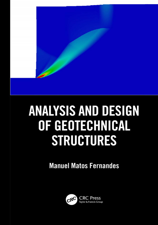
Analysis and Design of Geotechnical Structures First Edition by Manuel 9780429676154 0429676158
$50.00 Original price was: $50.00.$25.00Current price is: $25.00.
Analysis and Design of Geotechnical Structures First Edition Manuel Matos Fernandes – Ebook Instant Download/Delivery ISBN(s): 9780429676154, 0429676158

Product details:
- ISBN 10:0429676158
- ISBN 13: 9780429676154
- Author: Manuel
Analysis and Design of Geotechnical Structures
Table contents:
1 Geotechnical characterization: In situ testing
1.1 Introduction
1.2 Geotechnical investigation
1.2.1 Preliminary surface survey
1.2.2 Geophysical investigation
1.2.2.1 Introduction
1.2.2.2 Electrical resistivity method
1.2.2.3 Seismic refraction method
1.2.2.4 Spectral-analysis-of-surface-waves (SASW) method
1.2.2.5 Ground-penetrating radar (GPR)
1.2.3 Geomechanical investigation
1.2.3.1 Introduction
1.2.3.2 Trial pits and shafts
1.2.3.3 Borehole drilling
1.2.3.4 Rotary coring
1.2.4 Note on undisturbed soil sampling
1.2.4.1 Introduction
1.2.4.2 Direct sampling
1.2.4.3 Indirect sampling
1.2.4.4 Sampling of sands
1.3 In situ testing
1.3.1 Introduction
1.3.2 Standard penetration test (SPT)
1.3.2.1 Essential aspects of the equipment and test procedure
1.3.2.2 SPT corrections
1.3.2.3 Equipment calibration
1.3.2.4 Correlations of (N1)60 with soil properties and parameters
1.3.3 Cone penetrometer test (CPT/CPTu)
1.3.3.1 Essential aspects of the equipment and test procedure: measured parameters
1.3.3.2 Interpretation of results: soil classification charts
1.3.3.3 Correlations with soil characteristics and parameters
1.3.4 Dynamic probing test (DP)
1.3.4.1 Essential aspects of the equipment and test procedure
1.3.4.2 Comment regarding the use of dynamic probing tests: interpretation of results
1.3.5 Vane shear test (VST)
1.3.5.1 Essential aspects of the equipment and test procedure
1.3.5.2 Interpretation of test results for deriving cu
1.3.6 Plate load test (PLT)
1.3.6.1 Essential aspects of the equipment and test procedure
1.3.6.2 Interpretation of results
1.3.6.3 Final remark
1.3.7 Cross-hole seismic test (CHT)
1.3.7.1 Essential aspects of the equipment and test procedure
1.3.7.2 Interpretation of results
1.3.7.3 Final remark
1.3.8 Down-hole seismic tests
1.3.9 Self-boring pressuremeter test (SBPT)
1.3.9.1 Essential aspects of the equipment and test procedure
1.3.9.2 Interpretation of results
1.3.10 Ménard pressuremeter test (PMT)
1.3.10.1 Essential aspects of the equipment and test procedure
1.3.10.2 Interpretation of results
1.3.11 Flat dilatometer test (DMT)
1.3.11.1 Essential aspects of the equipment and test procedure
1.3.11.2 Interpretation of results
1.3.12 Tests for permeability characterization
1.3.12.1 Pumping tests
1.3.12.2 Borehole or Lefranc tests
1.4 Global overview on site characterization
1.4.1 Summary of in situ tests
1.4.2 In situ versus laboratory tests
1.4.2.1 Introduction
1.4.2.2 Advantages and limitations of laboratory tests
1.4.2.3 Advantages and limitations of in situ tests
1.5 Stiffness characterization by means of in situ and laboratory tests
1.5.1 General overview: definitions
1.5.2 Small is beautiful
1.5.3 Relation of the tests to the strain level in the soil
1.5.4 Methodology for characterization of soil stiffness for all strain levels
2 Overall stability of soil masses
2.1 Introduction
2.2 Introduction to limit analysis theory
2.2.1 Formulation: upper and lower bound theorems
2.2.2 Example of application – excavation with vertical face under undrained conditions
2.3 Limit equilibrium methods
2.3.1 Introduction
2.3.2 Method of slices: general formulation
2.3.3 Fellenius method
2.3.4 Simplified Bishop method
2.3.5 Spencer method
2.3.6 Comment
2.4 Stability of embankments on soft clayey soil
2.4.1 Introduction
2.4.2 Application of the method of slices in total stress analyses
2.4.3 Methods to improve stability conditions
2.4.3.1 Lateral stabilizing berms
2.4.3.2 Staged construction
2.4.3.3 Foundation soil reinforcement with stone columns
2.4.3.4 Reinforcement of the base of the embankment with geosynthetics
2.4.3.5 Use of lightweight aggregates as fill material
2.4.4 Comment
2.5 Unsupported cuts in clayey soil
2.5.1 Introduction: basic features
2.5.2 The question of safety and its evolution with time
2.5.3 Note about the maximum depth of tension cracks on the ground surface
2.5.4 Cuts under undrained conditions
2.5.4.1 Vertical cuts
2.5.4.2 Inclined face excavations
2.5.5 Excavations in drained conditions: effective stress analyses: Hoek and Bray charts
Annex A2.1 Stability analysis of embankments during staged construction
Annex A2.2 Stone column reinforcement oF the foundation of embankments on soft soil
Annex A2.3 Method of Leroueil and Rowe (2001) for the stability analysis of embankments oN soft soil with base reinforcement with geosynthetic
Annex E2 Exercises (resolutions are included in the Final Annex)
3 Basis of geotechnical design
3.1 Introduction
3.2 Variables and uncertainties in geotechnical design
3.3 Global safety factor method
3.3.1 Definition of global safety factor: typical values
3.3.2 Limitations of the global safety factor method
3.4 Limit state method and partial safety factors
3.4.1 General considerations
3.4.2 Distinct forms of application of the limit state method
3.5 Probabilistic methods
3.5.1 Safety margin, reliability index, and probability of failure
3.5.2 Application of probabilistic methods in geotechnical design
3.6 Introduction to Eurocode 7 – geotechnical design
3.6.1 The Structural Eurocodes: generalities
3.6.2 Design values of the actions, material properties, and geometric data
3.6.3 The question of the characteristic value of a geotechnical parameter
3.6.3.1 The concept of characteristic values of a structural and a geotechnical material parameter: Eurocode 0 versus Eurocode 7
3.6.3.2 The dependence on the structure and on the limit state under consideration
3.6.3.3 The dependence on the size of the ground region that affects a given limit state
3.6.4 Types of limit states
3.6.5 Verification of safety for STR and GEO limit states
3.6.6 The three design approaches
3.6.7 Comment about the justification for adopting a unit safety factor for the permanent actions
3.6.8 Final comment and perspectives
3.7 Application of LRFD: AASHTO Code (2012)
3.8 Note about Eurocode 8: definition of seismic action
Annex A3.1 Summary of some probabilistic concepts
Annex A3.2 Partial safety factors for the EQU, UPL AND HYD limit states, according to Eurocode 7
Annex A3.3 Design Approaches 1, 2 and 3 of Eurocode 7 for limit state types STR and GEO
A3.3.1 Partial safety factors on actions and the effect of actions
A3.3.2 Partial safety factors on material strengths and resistances
Annex A3.4 Resistance factors from LRFD bridge design specifications (AASHTO, 2012)
4 Consolidation theories and delayed settlements in clay
4.1 Introduction
4.2 Stress–strain relations in soils loaded under constrained conditions
4.2.1 Constrained loading: oedometer tests
4.2.2 Time effect: hydromechanical analogy
4.2.3 Load diagrams obtained in the oedometer test
4.2.4 Treatment of the compressibility curve
4.2.5 Parameters for the definition of the stress–strain relationships
4.2.6 Expressions for calculation of the consolidation settlement
4.2.7 Some practical issues
4.3 The Terzaghi consolidation theory
4.3.1 Base hypotheses: consolidation equation
4.3.2 Consolidation equation solutions
4.3.2.1 Layer with two draining boundaries
4.3.2.2 Layer with only one draining boundary
4.3.3 Consolidation settlement change over time
4.3.4 Estimation of cv from oedometer tests
4.3.5 Settlement change taking into account construction time
4.4 Loading in general (non-constrained) conditions
4.4.1 Introduction: generalization of the hydromechanical analogy
4.4.2 Consolidation settlement calculation: classical method of Skempton and Bjerrum
4.4.3 Two- and three-dimensional consolidation
4.4.3.1 Biot theory results
4.4.3.2 Solutions of Terzaghi’s theory for any distributions of the initial excess pore pressure
4.5 Secondary consolidation
4.5.1 Introduction
4.5.2 Overconsolidation by secondary consolidation
4.5.3 Secondary consolidation settlement: conventional and Brazilian approaches
4.6 Acceleration of consolidation
4.6.1 Introduction
4.6.2 Preloading
4.6.2.1 Base scheme
4.6.2.2 Calculation of the temporary surcharge
4.6.2.3 Comment: control of secondary consolidation settlements
4.6.3 Vertical drains
4.6.3.1 General scheme: types of drains – installation
4.6.3.2 Radial consolidation
4.6.3.3 Smear effect
4.6.3.4 Calculation of the vertical drain network
4.6.4 Vacuum preloading
4.6.5 Note on the use of stone columns
4.7 Observation of embankments on soft soil
4.7.1 Installation points, equipment, and parameters to monitor
4.7.2 The Asaoka method
Annex A4.1 Deduction of Equations
A4.1.1 Equation 4.1
A4.1.2 Constancy of the ratio h/(1 + e)
Annex A4.2 Evaluation of σ′p by the Casagrande construction
Annex A4.3 Treatment of log σ′v –e curves by the Schmertmann construction
Annex A4.4 Evaluation of the vertical consolidation coefficient, cv
A4.4.1 The Taylor method
A4.4.2 The Casagrande method
Annex E4 Exercises (resolutions are included in the Final Annex)
5 Earth pressure theories
5.1 Introduction
5.2 Rankine’s active and passive limit equilibrium states
5.2.1 Introduction of the concept
5.2.2 Earth pressure coefficients: coefficients of active and passive earth pressure, according to Rankine
5.2.3 Active and passive thrusts according to Rankine
5.3 Displacements associated with active and passive states
5.3.1 Terzaghi experiments
5.3.2 Stress paths: typical results of triaxial tests
5.3.3 Consequences for the design of civil engineering structures
5.4 Generalization of Rankine’s method
5.4.1 Introduction
5.4.2 Vertical, uniformly distributed surcharges applied to the ground surface
5.4.3 Stratified ground
5.4.4 Ground with water table
5.4.5 Extension of Rankine’s theory to soils with cohesion
5.4.6 Extension of Rankine’s theory to soil masses with inclined surface interacting with vertical wall
5.4.7 Extension of Rankine’s theory to soil masses with inclined surface interacting with non-vertical wall
5.5 Boussinesq, Résal, and Caquot theories for the consideration of soil wall friction
5.5.1 Introduction
5.5.2 The Boussinesq theory: the Caquot-Kérisel tables
5.5.3 Cohesive soil masses: theorem of corresponding states
5.6 Coulomb’s theory
5.6.1 General presentation and hypotheses
5.6.2 Culmann construction
5.6.3 Determination of the thrust application point
5.6.4 Analytical solution
5.6.5 Thrust calculation due to uniform surcharge at the surface to be used in Coulomb’s method
5.6.6 Comparison of the Rankine, Caquot-Kérisel, and Coulomb methods
5.7 Active and passive thrusts under seismic conditions: Mononobe-Okabe theory
5.7.1 Introduction
5.7.2 Expression deduction
5.7.3 Critical horizontal acceleration
5.7.4 Inclination of the surfaces that limit the thrust wedges
5.7.5 Graphical solution of the problem
5.7.6 Thrust application point
5.7.7 Generalization to submerged soil masses
5.7.7.1 Introduction
5.7.7.2 Seismic thrust of a free water mass on a vertical wall
5.7.7.3 Thrust of a very permeable submerged soil mass
5.7.8 Note about the seismic thrusts on walls with null displacements
Annex A5.1 – Caquot–Kérisel tables (extract)
Annex E5 – Exercises (resolutions are included in the Final Annex)
The leaning bell-tower of Pisa
1 The tower
2 The ground
3 The tilt
4 The phenomenon
5 The stabilization works
6 Shallow foundations
6.1 Introduction
6.2 Bearing capacity under vertical loading
6.2.1 Introduction
6.2.2 General expression of the load-bearing capacity under vertical loading
6.2.3 Conditions of application of the bearing capacity equation: total and effective stress analyses
6.2.4 Influence of the parameters integrating the bearing capacity expression
6.2.5 Extension of the bearing capacity expression to cases of practical interest
6.2.5.1 Introduction
6.2.5.2 Eccentric loads
6.2.5.3 Corrective factors for the bearing capacity
6.2.5.4 Shallow foundations on stratified ground
6.2.6 Bearing capacity for vertical loading under seismic conditions
6.2.7 Safety against foundation soil failure due to insufficient bearing capacity for vertical loading
6.2.7.1 Global safety factor
6.2.7.2 Partial safety factors: structural Eurocodes and LRFD codes
6.3 Estimation of foundation settlement
6.3.1 Introduction
6.3.2 Immediate settlement: elastic solutions
6.3.2.1 General expression
6.3.2.2 Homogeneous semi-indefinite soil formation
6.3.2.3 Homogeneous layer with rigid lower boundary
6.3.2.4 Foundation rotation associated with moment action
6.3.2.5 Shortcomings of the elastic solutions
6.3.3 Immediate settlement in sand
6.3.3.1 Schmertmann’s method
6.3.3.2 Elastic theoretical method versus Schmertmann’s method
6.3.3.3 Deformation modulus of sandy soils
6.3.4 Immediate settlement in clay
6.3.4.1 Settlement expression
6.3.4.2 Deformation modulus of clayey soils
6.3.5 Note about settlement by secondary consolidation or by creep
6.3.6 Verification of structural serviceability limit states due to foundation movement: actions to consider
6.4 Design of the foundations of a structure
6.4.1 Movement of the foundation of a structure: definitions and limits
6.4.2 Sizing based on allowable stress or allowable pressure
6.4.3 Design based on identical foundation settlement
6.4.4 Allowable design settlement for structural foundations
6.4.5 Design sequence for shallow building foundations
6.5 Evaluation of site seismic behavior: liquefaction susceptibility of sandy soils
6.5.1 Introduction
6.5.2 The cyclic stress procedure: general formulation
6.5.2.1 Representation of seismic loading
6.5.2.2 Characterization of liquefaction potential
6.5.2.3 Evaluation of safety against liquefaction
6.5.3 The cyclic stress approach: more recent application proposals
6.5.3.1 Results from the NCEER Workshops, USA (1996, 1998)
6.5.3.2 New developments from Idriss and Boulanger
6.5.4 Settlement evaluation in sand formations above the water table
6.5.5 Ground improvement for liquefaction mitigation
6.5.5.1 Most common densification methods for sand strata
6.5.5.2 Degree of improvement to be achieved and area to be treated
Annex A6.1 Evaluation of the bearing capacity for vertical loading by direct application of PMT results (Melt, 1993)
Annex A6.2 Incremental Stress in an elastic, homogeneous half-space loaded at the surface
A6.2.1 Solutions of Boussinesq and Flamant and “stress bulbs”
A6.2.2 Uniform pressure on infinite strip
A6.2.3 Triangular pressure on infinite strip
A6.2.4 Uniform pressure on circular area
A6.2.5 Uniform pressure on rectangular area
Annex A6.3 Settlement evaluation by direct application of PMT results (Melt, 1993)
Annex E6 exercises (resolutions are included in the Final Annex)
7 Pile foundations
7.1 Introduction
7.2 Types of pile foundations and construction methods
7.3 Single axially loaded pile
7.3.1 Shaft and base resistance mobilization
7.3.2 Influence of the construction process on pile axial resistance
7.4 Ultimate resistance of a single axially loaded pile
7.4.1 Bearing capacity
7.4.2 Assessment from analytical methods
7.4.2.1 Base resistance
7.4.2.2 Shaft resistance
7.4.3 Assessment from semi-empirical methods based on field tests
7.4.3.1 General aspects
7.4.3.2 Method based on CPT and PMT results (French or LCPC method)
7.4.3.3 Methods based on SPT results
7.4.3.4 Pile resistance in hard soil/soft rock
7.4.4 Assessment from axial load tests
7.4.4.1 General
7.4.4.2 Conventional static load test (compression)
7.4.4.3 Bi-directional (Osterberg) load test
7.4.4.4 Assessment from high-strain dynamic load tests
7.5 A note on negative skin friction
7.6 Single laterally loaded pile
7.6.1 Basic phenomenology of the soil–pile interaction for rigid and slender piles
7.6.2 Structural analysis of slender piles
7.6.2.1 Soil–structure interaction
7.6.2.2 Winkler theory: analytical solutions
7.6.2.3 P-y curves approach
7.7 Pile groups
7.7.1 General aspects
7.7.2 Group effect in axially loaded piles
7.7.3 Group effect in laterally loaded piles
7.7.3.1 Method of the influence factors
7.7.3.2 P-multipliers method
7.8 Integrity pile testing
7.8.1 General
7.8.2 Sonic-echo test
7.8.3 Cross-hole test
7.9 Introduction of safety
7.9.1 General
7.9.2 Global safety factors
7.9.3 Partial safety factors (Eurocode 7)
7.9.3.1 Ultimate compressive resistance from static load tests
7.9.3.2 Ultimate compressive resistance from ground test results
7.9.3.3 Ultimate compressive resistance from dynamic impact tests
7.9.4 Load and Resistance-Factored Design (LRFD)
Annex A7.1 Evaluation of the pile axial capacity by direct application of PMT or CPT results
Annex E7 Exercises
E7.1
E7.2
E7.3
E7.4
E7.5
E7.6
8 Earth-retaining structures
8.1 Introduction
8.2 Gravity walls
8.2.1 Wall types: conception
8.2.2 Ultimate limit states of gravity walls by external failure
8.2.3 Soil thrust to be considered for the evaluation of external safety
8.2.4 Practical questions about design and construction
8.2.4.1 Parameters of the soil and interfaces
8.2.4.2 Backfill drainage
8.2.5 Evaluation of the soil thrust in some practical cases
8.2.5.1 Consideration of seepage forces
8.2.5.2 Retaining walls with a non-rectilinear back face
8.2.5.3 Reinforced concrete cantilever walls
8.2.5.4 Pressure induced by point loads or uniform surcharges applied on a limited surface area
8.2.6 Evaluation of the external safety of gravity retaining walls
8.2.6.1 Global safety factors
8.2.6.2 Verification of safety by the partial safety factor method: application of Eurocode 7
8.2.6.3 Gravity retaining walls under seismic action: selection of kh and kv
8.2.7 Internal design
8.2.7.1 General considerations
8.2.7.2 Reinforced concrete retaining walls
8.2.7.3 Stone masonry, gabion, and cyclopean concrete retaining walls
8.3 Embedded flexible walls
8.3.1 Introduction
8.3.2 Cantilever embedded walls
8.3.2.1 Analysis methods: safety factors
8.3.2.2 Brief parametric study
8.3.2.3 Vertical equilibrium of cantilever embedded walls
8.3.3 Single-propped embedded walls
8.3.3.1 Analysis method: safety factors
8.3.3.2 Brief parametric study
8.3.3.3 Vertical equilibrium of single-propped and single-anchored walls
8.3.4 Note on water-related pressure
8.3.5 Construction sequence combining cantilever and single-propped walls in distinct stages
8.4 Anchors
8.4.1 Introduction: terminology and execution
8.4.2 Mechanical behavior of anchors
8.4.2.1 Limit states: force-displacement graph
8.4.2.2 Mobilization of the grout bulb–ground interface resistance
8.4.3 Anchor design
8.4.3.1 Limit State Design
8.4.3.2 Estimation of anchor resistance: anchor load tests and the role of comparable experience
8.4.3.3 Estimation of anchor resistance from tests
8.4.3.4 Confirmation of the anchorage resistance from the results of the acceptance tests
8.4.3.5 Aspects concerning geometry
8.4.3.6 Verification of global stability
Annex A8.1 Seismic coefficients for design of retaining walls, according to Eurocode 8
Annex E8 Exercises (resolutions are included in the Final Annex)
The Vajont catastrophe
9 Stability and stabilization of natural slopes
9.1 Introduction
9.2 Infinite slopes
9.2.1 Introduction: geological-geotechnical scenarios
9.2.2 Infinite slope in granular material, above the ground water level
9.2.3 Infinite slope in a material with cohesion and angle of shearing resistance, above the ground water level
9.2.4 Infinite slope with seepage parallel to the ground surface
9.2.4.1 Introduction
9.2.5 Infinite slope under seismic action
9.3 General method for slope stability analysis: the Morgenstern and Price method
9.3.1 Introduction
9.3.2 Hypotheses
9.3.3 Equilibrium equations for a slice of infinitesimal width
9.3.4 Solution of the system of equations
9.4 Method of sliding wedges
9.5 Context of slope stability studies
9.5.1 Introduction
9.5.2 Active zone, passive zone, and neutral line in a natural slope
9.5.3 Circumstances and symptoms of slope instability
9.5.4 Interpretation of the potential failure mechanism
9.5.5 Stages of slope movements: reactivation of landslides
9.5.6 Note on factor of safety
9.6 Stabilization measures
9.6.1 Introduction
9.6.2 Alteration of the slope geometry
9.6.3 Superficial and deep drainage
9.6.4 Structural solutions
9.6.4.1 Ground anchors connected to reinforced concrete walls
9.6.4.2 Ground reinforcement with inclusions that intersect the failure surface
9.6.5 Methods of analysis of the stabilization solutions
9.7 Observation of natural slopes
9.7.1 General remarks
9.7.2 Observation plan
Annex A9.1 Seismic coefficients to be used in slope stability analyses, according to Eurocode 8
Annex A9.2 Inclinometer measurements
A9.3 In situ measurement of pore water pressure
Annex E9 exercises (resolutions are included in the Final Annex)
10 Introduction to earthworks: Soil compaction
10.1 Introduction
10.2 Compaction
10.2.1 Compaction curves
10.2.1.1 The w−γd relationship in soils with a significant fraction of fines
10.2.1.2 Effect of the compaction effort
10.2.1.3 The w − γd relationship in clean granular soils
10.2.2 Laboratory compaction tests
10.2.2.1 Proctor tests
10.2.2.2 Vibration compaction tests
10.2.2.3 Compaction parameters of soils with coarse gravel (material retained in the 19-mm sieve)
10.2.3 Field compaction equipment
10.2.4 Mechanical behavior of compacted soils
10.2.4.1 Introduction: soils with significant fines content and the effect of soil suction
10.2.4.2 Dam failures during construction and the practice of compacting on the dry side of the optimum
10.2.4.3 Volume change in a soil saturated by inundation. The phenomenon of soil collapse
10.2.4.4 Compaction charts
10.3 Introduction to earthworks
10.3.1 The peculiar context of earthwork design and construction
10.3.2 Selection of materials
10.3.3 Assessment of the compaction characteristics: mechanical and hydraulic characterization
10.3.4 Phase of conception and design
10.3.5 Specifications for field compaction
10.3.6 Field compaction
10.3.7 Control of compaction through physical characteristics
10.3.7.1 Conventional process
10.3.7.2 Control by Hilf’s Rapid Method
10.3.7.3 Frequency of the compaction control operations and statistical analysis of results
10.3.8 Control of the compaction through mechanical characteristics
10.3.8.1 Control by means of soil testing
10.3.8.2 Control using a compaction plant: intelligent compaction
10.3.9 Final remarks
References
Final annex: Resolution of the exercises
Symbols
Index
People also search:
analysis and design of geotechnical structures
what is geotechnical analysis
geotechnical analysis of soil
geotechnical structures examples
analysis and design of geotechnical structures pdf
what is structural analysis and design
You may also like…
Uncategorized
Matrix Discrete Element Analysis of Geological and Geotechnical Engineering 1st Edition Chun Liu
Engineering - Civil & Structural Engineering
Engineering - Civil & Structural Engineering
Fire Resistant Design of Structures 1st Edition Srinivasan Chandrasekaran
Earth Sciences - Geology
Pressuremeters in Geotechnical Design 2nd Edition by BG Clarke ISBN 9780367464684 2022021398
Housekeeping & Leisure - Interior Design & Decoration
Advanced Design Examples of Seismic Retrofit of Structures Mohammad Yekrangnia
Engineering - Civil & Structural Engineering
Matrix Discrete Element Analysis of Geological and Geotechnical Engineering Liu

