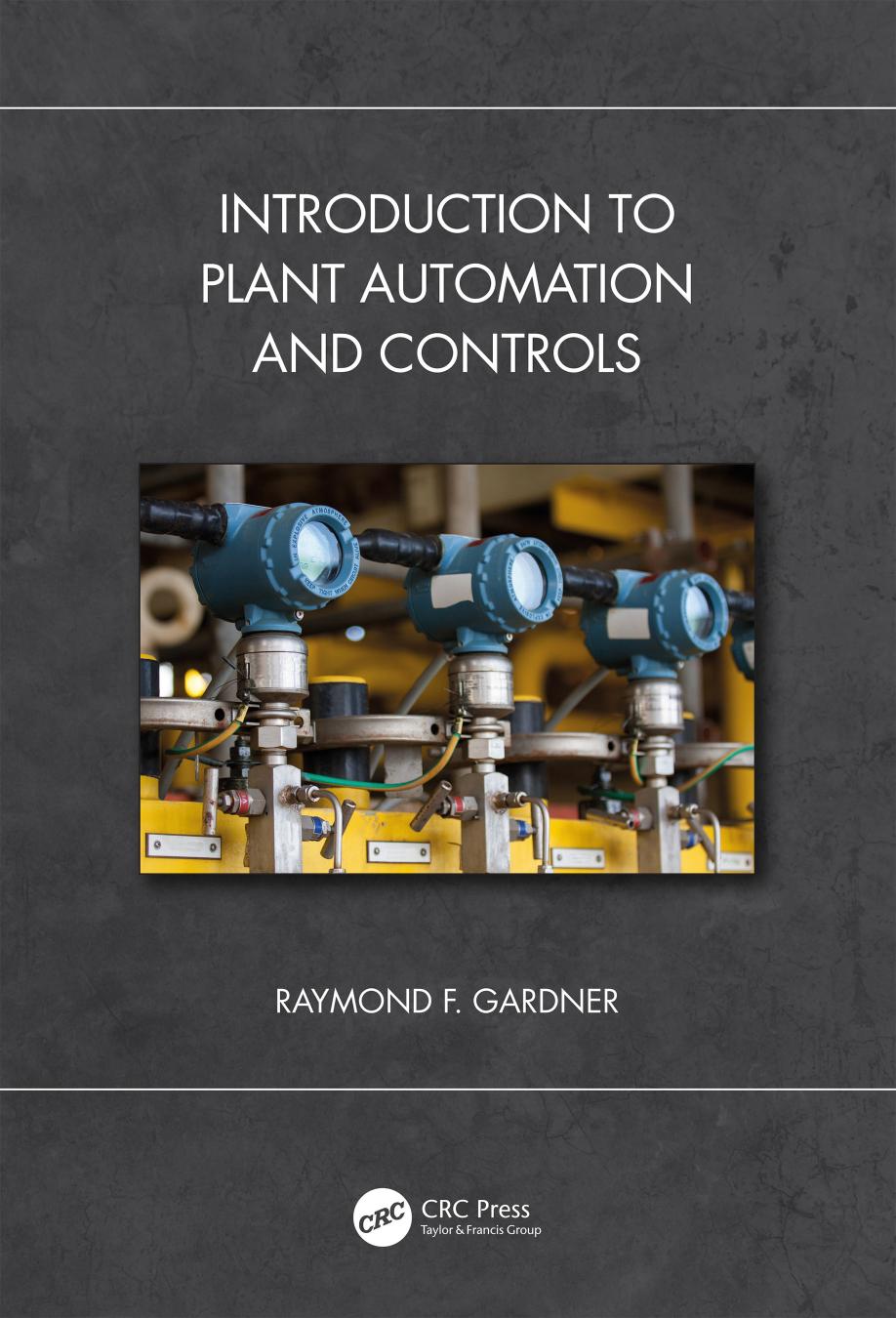
Introduction to Plant Automation and Controls 1st Edition by Raymond F Gardner ISBN 9780367494209 0367494205
$50.00 Original price was: $50.00.$25.00Current price is: $25.00.
Introduction to Plant Automation and Controls 1st Edition by Raymond F Gardner – Ebook PDF Instant Download/Delivery: 9780367494209 ,0367494205
Full download Introduction to Plant Automation and Controls 1st Edition after payment

Product details:
ISBN 10: 0367494205
ISBN 13: 9780367494209
Author: Raymond F Gardner
Introduction to Plant Automation and Controls 1st Edition Table of contents:
Chapter 1 Measurement fundamentals and instrumentation
INSTRUMENTATION DEFINITIONS
GAGE ACCURACY
GAGE SELECTION
CALIBRATION STANDARDS
CALIBRATION OF INSTRUMENTATION
PRESSURE CONVERSION
PRESSURE GAGES
Pressure measurement
Manometer (U-tube)
Bourdon tube pressure gage
Pressure transducer
Calibrating pressure gages
Temperature measurement
LIQUID-EXPANSION THERMOMETER
FILLED-SYSTEM THERMOMETER
BIMETALLIC-ELEMENT THERMOMETER
ELECTRONIC TEMPERATURE MEASUREMENT DEVICES
Thermocouple
Thermistor
Resistance temperature detector (RTD)
Calibration of a 4-20mA sensor
Verification of the RTD sensor
Calibration of the 4-20mA transmission signal
Calibration of the digital meter
TANK LIQUID-LEVEL MEASUREMENT
Gage glasses, petcocks, and sounding tube
Ultrasonic or radar level transmitters
Pneumercators
Pressure transducers and liquid level measurement
Magnetic float level transmitters
DIFFERENTIAL PRESSURE AND DIFFERENTIAL-PRESSURE TRANSMITTERS
Flow measurement
Positive-displacement totalizing meters
Differential-pressure flow meters
Velocity flow meters
Vortex-shedding flow meter
Turbine flow meter
Non-intrusive flow meters/transmitters
Viscosity measurement
VIBRATION MEASUREMENT
Accelerometer
Notes
Chapter 2 Control terminology, theory, and tuning
OPEN- AND CLOSED-LOOP CONTROL
MODES OF CONTROL
On-off control
Proportional control with feedback
Feedforward control
Proportional control
Gain and proportional band
Offset
Instability and hunting
Integral or reset control
Derivative or rate control
Pneumatic control: nozzle-flapper, pneumatic relays, and PID control
Nozzle-flapper systems
Proportional-only control with open-loop gain
Proportional-only with adjustable closed-loop gain
PI proportional with integral or reset control
PID control—The derivative or rate function
Pneumatic PD control
Pneumatic P, PI, PD, and PID control
TUNING THE PID CONTROLLER
Ziegler-Nichols closed-loop method
Open loop tuning
STABILITY
Chapter 3 Basic electronics
DIODE
FILTERS
VOLTAGE DIVIDER
ZENER DIODE
BIPOLAR JUNCTION TRANSISTOR (BJT)
BIASING
THYRISTOR OR SILICON-CONTROLLED RECTIFIER (SCR)
GATE TURN-OFF THYRISTORS (GTOS)
DIACS AND TRIACS
FIELD-EFFECT TRANSISTOR (FET)
INSULATED-GATE BIPOLAR TRANSISTOR (IGBT)
Notes
Chapter 4 Digital theory, logic, and two-state control
BOOLEAN LOGIC
COMBINATIONAL LOGIC AND BOOLEAN ALGEBRA
The universal NAND gate
INTRODUCTION TO KARNAUGH MAPS
Example 4:
Example 5:
SEQUENTIAL LOGIC AND FLIP-FLOPS
The set-reset (or S-R) flip-flop
The J-K flip-flop
COMBINATIONAL LOGIC USING SWITCHES
SEQUENTIAL LOGIC USING CONTROL RELAYS
DIODES AND TRANSISTOR SWITCHING LOGIC: CONSTRUCTING DIGITAL-CIRCUIT GATES
Diode logic (DL)
Diode-transistor logic (DTL)
Transistor-transistor (TTL)
Chapter 5 Motor controllers
SWITCHES AND ELECTRICAL DEVICES
MOTOR CONTROLLER /COMBINATION STARTER CONSTRUCTION
MOTOR CONTACTORS
CONTROL RELAYS
SOLID-STATE RELAYS AND CONTACTORS
SPECIALTY RELAYS
Timing relays
Latching relays
Alternating relays
INTERPOSING RELAYS
LEAD-LAG CONTROLLERS
ONE-SHOT, WATCHDOG, AND OTHER TIMERS
NEMA RATINGS
MOTOR CONTROLLER DIAGRAMS
LOW-VOLTAGE PROTECTION/LOW-VOLTAGE RELEASE
REVERSING MOTORS
JOGGING MOTORS
REDUCED-VOLTAGE STARTING
Multi-speed motors
Wound-rotor induction motor—Multiple speed and reduced-current starting
Wye-delta reduced-voltage starting
Part-winding reduced current starters
Primary resistor/primary reactor/autotransformer
Primary-resistor starting
Primary-reactor starting
Autotransformers
Example 1
Electronic solid-state soft start
Variable-frequency drives
Notes
Chapter 6 Variable-frequency drives and harmonics
VARIABLE-FREQUENCY DRIVES (VFDS)
VFD DESIGN
Voltage-source inverters (VSI)
Phase-controlled current-source inverters (CSI)
Load-commuted inverters (LCI)
Cycloconverters (CCV)
Pulse-width modulation (PWM)
Flux-vector drives
VFD voltage control
Soft starters
HARMONICS
Harmonics in the time and frequency domains
CAUSES OF HARMONICS
Linear loads
Non-linear loads
CLASSIFICATION OF HARMONIC TYPES
Positive-, negative-, and zero-sequence harmonics
Triplens
Intraharmonics and subharmonics
Third harmonic
Harmonics from the front-end rectifier section
Percent total harmonic distortion
Reflected waves
Notching
HARMONICS MITIGATION TECHNIQUES
Dc link choke
Ac line reactor
Tuned harmonic filters
Multi-pulse transformers
Delta-to-delta-wye multi-phase transformer
Multi-tap, multiphase transformer
Active front ends
dv/dt filters
HARMONICS AND POWER QUALITY ANALYZERS
Quantifying harmonics severity
Example
Solution method 1
Solution method 2
Power-quality measurement
CONCLUSION
Notes
Chapter 7 Boiler controls
BURNER-MANAGEMENT SYSTEM AND FLAME SAFEGUARD SYSTEM (FSS)
Check permissives and interlocks
Boiler pre-purge
Ignition attempt
Flame detection
Release to modulate
Burner normal cycling
Boiler operation during load changes
Burner management permissives
Burner safety shutdown
Boiler trips
COMBUSTION-CONTROL SYSTEM
Control symbols
Single-element and two-element combustion control systems
Boiler control schemes
Series versus parallel combustion-control systems
Parallel positioning using single-point positioning
Metered series combustion-control systems
Fully metered parallel positioning
Fully metered parallel positioning with cross-limiting
Two-element combustion-control system (parallel positioning with cross-limiting)
Two-element combustion-control system parallel positioning with cross-limiting and O2 trim
7.3 BOILER FEEDWATER SYSTEMS AND CONTROL
Single-element feedwater regulators
Problems with intemittent single-element control
Multi-element feedwater regulation systems
Interactions affecting drum water level and combustion-control systems
Feed pump pressure control
FORCED DRAFT, INDUCED DRAFT, AND FURNACE DRAFT CONTROL
SUPERHEATER TEMPERATURE CONTROL AND DESUPERHEATED STEAM
FUEL SELECTION AND POLLUTION MITGATION
Notes
Chapter 8 Pump and fan controls
PUMP CURVES
CONDENSATE CONTROL SYSTEMS
POSITIVE-DISPLACEMENT PUMPS
FANS, FAN CURVES, AND FAN CONTROL
FAN CONTROL
Notes
Chapter 9 Control valves
SELF-CONTAINED PRESSURE REDUCING VALVES
SELF-CONTAINED TEMPERATURE REGULATING VALVES
PNEUMATIC PILOT-ACTUATED CONTROL VALVES
PNEUMATIC PILOT CONTROLLER
PNEUMATIC ACTUATORS AND POSITIONERS
DIRECT ACTING/REVERSE ACTING AND FAIL-SAFE POSITION
LEVEL CONTROL
VALVE RESPONSE—HYSTERESIS AND DEADBAND
CONSTRUCTION TECHNIQUES TO IMPROVE PERFORMANCE
SIZING CONTROL VALVES FOR LIQUID APPLICATIONS
INSTALLATION CURVE
SIZING CONTROL VALVES FOR COMPRESSIBLE-FLOW APPLICATIONS
FLASHING AND CAVITATION
RECOVERY COEFFICIENT
CHOKED FLOW: COMPRESSIBLE AND INCOMPRESSIBLE FLUIDS
SELECTING THE VALVE Cv USING MANUFACTURER PRODUCT DATA
Example problem
ANSI VALVE CLASS
MOTOR ACTUATORS
CONTROL VALVE SELECTION GUIDELINES
Notes
Chapter 10 Speed, load, and alternator control
SPEED-LIMITING GOVERNORS
Speed-limiting protection
Low-lube-oil-pressure protection
Low-lube-oil pressure adjustment
Speed-limiting governor adjustment
CONSTANT-SPEED GOVERNORS
Mechanical-hydraulic governors
Governor droop and deadband
Equation 1a
Equation 1b
Governor compensation and isochronous control
Two-element governor
Load-sensing element
Flyweight speed-sensing element
Electronic constant speed governor
Governor linkage
Parallel operation of alternators
Paralleled alternators, both with drooping governors
Paralleled alternators, one isochronous and the other with a drooping governor
Other alternator controls
OVERSPEED TRIP DEVICES
Mechanical overspeed trip
Electronic overspeed trip
Other safety shutdown devices
Notes
Chapter 11 Programmable-logic controllers and operation
PLC HISTORY
MODERN PLCS
PLCS IN POWER PLANT CONTROL
PARTS OF THE PLC
Power supply
Central processing unit (CPU)
Memory
ROM
RAM
EPROM
EEPROM
Nonvolative RAM
Input devices
Digital input devices
Analog input devices
Output devices
Cabling and interfaces
Human-machine interface (HMI)
Control signals and signal isolation
GENERAL PLC TROUBLESHOOTING
NETWORKING THE PLC
PROGRAMMING THE PLC
PROGRAM EXECUTION
Relay logic
FUNCTIONS WITHIN PLCS
USING ALLEN-BRADLEY/ROCKWELL AUTOMATION RSLOGIX 500 SOFTWARE
UPLOADING/DOWNLOADING THE PROGRAM
ADDRESSING THE PLC DEVICES
Chapter 12 Wiring PLCs and I/O devices
PLC POWER-SUPPLY SYSTEMS
PLC INPUT AND OUTPUT DEVICES
Solid-state digital input and digital output devices
Sourcing and sinking
Flexible, polarity-independent transistor-based digital I/O devices
Other PLC output-module options
Mechanical relay outputs
High-power DC outputs
AC solid-state relay output
Note
Chapter 13 Allen-Bradley RSLogix software and ladder-diagram programming
ROCKWELL/ALLEN-BRADLEY PLC SOFTWARE
FUNCTIONS WITHIN PLCS
Discrete control/combinational logic
Sequential control
Continuous control
RSLINX, BOOT-DHCP TOOL, AND ESTABLISHING COMMUNICATIONS
RSLinx
BOOTP-DHCP
UPLOADING/DOWNLOADING THE PROGRAM
RS LOGIX PROGRAMMING
TERMS USED WITH PLC LADDER LOGIC PROGRAMMING:
Rack
Rung
Instruction
Bit
Bits, bytes, and words
Hardwired inputs and outputs
Line-smart/page smart numbering
Address
Bitbox
Internal contacts and internal coils
INTERNAL CONTACTS—EXAMINE IF CLOSED (XIC)
INTERNAL CONTACTS—EXAMINE IF OPEN (XIO)
INTERNAL COILS—OUTPUT ENERGIZE (OTE)
OUTPUT LATCH (OTL)/ OUTPUT UNLATCH (OTU)
ONE-SHOT (ONS)/ONE-SHOT RISING (OSR)/ONE-SHOT FALLING (OSF)
TIMERS—ON-TIME DELAY (TON) and OFF-TIME DELAY (TOF)
COUNTERS—COUNT UP (CTU) AND (CTD)
SWITCH BOUNCE AND COUNTERS
ARITHMETIC FUNCTIONS AND STATUS FILE (S2)
Status file
ADDRESSING AND PLC OPERATION
PLC INPUT/OUTPUT DATA LINKS
THE PROGRAM SCAN
FLOW CHARTS AND PSEUDOCODE
ANTICIPATING PROBLEMS WITH PROGRAM LOGIC
DOCUMENTING THE RSLOGIX PROGRAM
SAFETY CONSIDERATIONS DURING PROGRAMMING
Notes
Chapter 14 Electronic 4–20mA analog signals
TWO-WIRE 4–20MA CURRENT LOOP TRANSMITTERS
DETERMINING THE POWER SUPPLY VOLTAGE
CREATING THE 4-20MA TRANSMITTER SIGNAL
GROUND LOOPS: GROUNDING AND ISOLATED INSTRUMENTS
HART COMMUNICATION PROTOCOL
SUMMARY
Chapter 15 Analog functions using Allen-Bradley’s RSLogix software
ANALOG INPUT AND OUTPUT
Signal input and transmission
Signal conversion to machine language
Signal processing
Output signal and transmission
GETTING THE SIGNAL INTO THE PLC
USING THE PLC’S ANALOG SIGNAL
SCALING THE ANALOG SIGNAL
PROBLEM 1: ANALOG-INPUT FOR A PRESSURE TRANSMITTER
PROBLEM 2: ANALOG-OUTPUT FOR A CONTROL VALVE
PROBLEM 3: ANALOG-OUTPUT FOR A VARIABLE FREQUENCY DRIVE (VFD)
PROGRAMMING ANALOG PROPORTIONAL-INTEGRAL-DERIVATIVE APPLICATIONS
SUBROUTINES: LADDER LOGIC RELATED TO COMPUTER PROGRAMMING
SUMMARY
Notes
Chapter 16 IEC 61131-3 PLC programming languages (LD, FBD, SFC, ST, and IF)
THE PROGRAM STRUCTURE
LADDER DIAGRAM (LD)
FUNCTION BLOCK DIAGRAM (FBD)
SEQUENTIAL FUNCTION CHART (SFC)
Program operation
STRUCTURED TEXT (ST)
INSTRUCTION LIST (IL)
Syntax
SUMMARY
Note
Chapter 17 Centralized control systems, DCS, and SCADA
PLANT CONTROL ARCHITECTURES
CENTRALIZED CONTROL AND MONITORING SYSTEM
CENTRALIZED CONTROL SYSTEM
DCS AND SCADA SYSTEMS
SCADA system components
Remote communications
Designing the automation and controls systems
Panel layout drawings
I&C plan & elevation drawings
Instrumentation & controls wiring diagrams
Instrumentation & controls schedules (I&C)
DCS and SCADA communications architecture
PLC wiring diagrams (Figures 17.17, 17.18, and 17.19)
SCADA system screens
Programming the HMI device
Security
Define:
Chapter 18 PLC cabling, data transmission, and networking
SENSOR/TRANSDUCER CABLING—SIGNAL, POWER, EMI/RFI, SHIELDING, AND GROUNDING
SCADA AND DCS CABLING AND DATA TRANSMISSION
CATEGORY 5 AND CATEGORY 6 ETHERNET TCP/IP CABLE
FIBER-OPTIC DATA-TRANSMISSION CABLING
NETWORKING ARRANGEMENTS
INDUSTRIAL NETWORK STANDARDS
Modbus, Profibus, Ethernet/IP
Modbus
Profibus
Notes
Chapter 19 Industrial control system security
SCADA SYSTEM
ICS NETWORKING ARCHITECTURE SECURITY
THREAT TYPES
THREAT-MITIGATION STRATEGIES
Physical access
Hardware
Computer, SCADA, and internet access practices
General PLC programming and operation practices
Chapter 20 PLC terms and definitions
PROGRAMMABLE LOGIC CONTROLLERS AND COMPUTERS
Address
Binary coded decimal (BCD)
Bit
Byte
Central processing unit (CPU)
Electrically erasable programmable read-only memory (EEPROM)
Erasable programmable read-only memory (EPROM)
Image register/image table
Index register
Millisecond
Operator interface
Random-access memory (RAM)
Read-only memory (ROM)
Register
Shift register
Word
PLC INPUT/OUTPUT
Analog input (A/I)
Analog output (A/O)
Analog-to-digital converter (A/D)
Digital-to-analog converter (D/A)
Distributed control system (DCS)
Input module
I/O points
Output module
SCADA (supervisory control and data acquisition)
Transducer
PLC PROGRAMMING
Expression
Function
Instruction
Procedure
Program
Programming device
Routine
Software
Statement
Subroutine
Syntax
PLC DATA TRANSFER
Bandwidth
Baud rate
Collision detection
Ethernet
Master-slave protocol (client-server)
Media-access control (MAC)
Modbus protocol
Modem
Network
Nodes
Packet
Parallel communication
Peer-to-peer network
Polling/Query
Port
Profibus DP
Protocol
RS485 (or TIA-485)
Serial communication
Socket
Supervisory control and data acquisition (SCADA)
Switch or switching hub
Token ring
Transmission control protocol/Internet protocol (TCP/IP)
Index
People also search for Introduction to Plant Automation and Controls 1st Edition:
introduction to building automation systems
manufacturing plant automation
what is a plant in a control system
introduction to automatic control systems
plant automation engineer
Tags: Raymond F Gardner, Plant Automation, Controls
You may also like…
Biology and other natural sciences - Cytology
Plant Proteases and Plant Cell Death Marina Klemenčič Simon Stael Pitter F Huesgen
Computers - Networking
Introduction to Ansible Network Automation: A Practical Primer 1st Edition Brendan Choi
Engineering - Electrical & Electronic Engineering
Science Fiction - Fantasy Fiction
Computers - Programming
Uncategorized
Introduction to Plant Fossils 2nd Edition by Christopher J. Cleal 9781108624756 1108624758
Computers - Networking
Introduction to Ansible Network Automation: A Practical Primer Brendan Choi


